
Ceramic capacitor
2015/7/17
The different ceramic materials used for ceramic capacitors, paraelectric or ferroelectric ceramics, influences the electrical characteristics of the capacitors. Using mixtures of paraelectric substances based on titanium dioxide results in very stable and linear behavior of the capacitance value within a specified temperature range and low losses at high frequencies. But these mixtures have a relatively low permittivity so that the capacitance values of these capacitors are relatively small. Higher capacitance values for ceramic capacitors can be attained by using mixtures of ferroelectric materials like barium titanate together with specific oxides. These dielectric materials have much higher permittivities, but at the same time their capacitance value are more or less nonlinear over the temperature range, and losses at high frequencies are much higher. These different electrical characteristics of ceramic capacitors requires to group them into “application classes”. The definition of the application classes comes from the standardization. As of 2013, two sets of standards were in use, one from International Electrotechnical Commission (IEC) and the other from the now-defunct Electronic Industries Alliance (EIA).
Unfortunately the definitions of the application classes given in the two standards are different. The following table shows the different definitions of the application classes for ceramic capacitors:
|
Different definitions of application classes for ceramic capacitors |
|
|
Definition regarding to |
Definition regarding to |
|
Class 1 ceramic
capacitors |
Class I (or
written class 1) ceramic capacitors |
|
Class 2 ceramic
capacitors |
Class II (or
written class 2) ceramic capacitors |
|
Class 3 ceramic
capacitors |
Class III (or
written class 3) ceramic capacitors |
|
- |
Class IV (or
written class 4) ceramic capacitors |
Manufacturers, especially in theUS, preferred Electronic Industries Alliance (EIA) standards. In many parts very similar to the IEC standard, the EIA RS-198 defines four application classes for ceramic capacitors.
The different class numbers within both standards are the reason for a lot of misunderstandings interpreting the class descriptions in the datasheets of many manufacturers. The EIA ceased operations on February 11, 2011, but the former sectors continue to serve international standardization organizations.
In the following, the definitions of the IEC standard will be preferred and in important cases compared with the definitions of the EIA standard.
Class 1 ceramic capacitors
Class 1 ceramic capacitors are accurate, temperature-compensating capacitors. They offer the most stable voltage, temperature, and to some extent, frequency. They have the lowest losses and therefore are especially suited for resonant circuit applications where stability is essential or where a precisely defined temperature coefficient is required, for example in compensating temperature effects for a circuit. The basic materials of class 1 ceramic capacitors are composed of a mixture of finely ground granules of paraelectric materials such as Titanium dioxide (TiO
2), modified by additives of Zinc, Zirconium, Niobium, Magnesium, Tantalum, Cobalt and Strontium, which are necessary to achieve the capacitor’s desired linear characteristics.
The general capacitance temperature behavior of class 1
capacitors depends on the basic paraelectric material, for example TiO
2. The additives of the chemical composition are used to adjust precisely
the desired temperature characteristic. Class 1 ceramic capacitors have the
lowest volumetric efficiency among ceramic capacitors. This is the result of the
relatively low permittivity (6 to 200) of the paraelectric materials. Therefore, class 1 capacitors
have capacitance values in the lower range.
|
Ceramic materials for class 1 ceramic capacitors |
||
|
Chemical- |
Relative permittivity |
Temperature- |
|
MgNb2O6 |
21 |
−70 |
|
ZnNb2O6 |
25 |
−56 |
|
MgTa2O6 |
28 |
18 |
|
ZnTa2O6 |
38 |
9 |
|
(ZnMg)TiO3 |
32 |
5 |
|
(ZrSn)TiO4 |
37 |
0 |
|
Ba2Ti9O20 |
40 |
2 |
Class 1 capacitors have a temperature coefficient that is typically fairly linear with temperature. These capacitors have very low electrical losses with a dissipation factor of approximately 0.15%. They undergo no significant aging processes and the capacitance value is nearly independent of the applied voltage. These characteristics allow applications for high Q filters, in resonant circuits and oscillators (for example, in phase-locked loop circuits).
The EIA RS-198 standard codes ceramic class 1 capacitors with a three character code that indicates temperature coefficient. The first letter gives the significant figure of the change in capacitance over temperature (temperature coefficient α) in ppm/K. The second character gives the multiplier of the temperature coefficient. The third letter gives the maximum tolerance from that in ppm/K. All ratings are from 25 to 85 °C:
|
Class 1-ceramic capacitors |
||
|
Temperature coefficient α |
Multiplier |
Tolerance |
|
C: 0.0 |
0: -1 |
G: ±30 |
|
B: 0.3 |
1: -10 |
H: ±60 |
|
L: 0.8 |
2: -100 |
J: ±120 |
|
A: 0.9 |
3: -1000 |
K: ±250 |
|
M: 1.0 |
4: +1 |
L: ±500 |
|
P: 1.5 |
6: +10 |
M: ±1000 |
|
R: 2.2 |
7: +100 |
N: ±2500 |
|
S: 3.3 |
8: +1000 |
|
|
T: 4.7 |
|
|
|
V: 5.6 |
|
|
|
U: 7.5 |
|
|
In addition to the EIA code, the temperature coefficient of the capacitance dependence of class 1 ceramic capacitors is commonly expressed in ceramic names like “NP0”, "N220" etc. These names include the temperature coefficient (α). In the IEC/EN 60384-8/21 standard, the temperature coefficient and tolerance are replaced by a two digit letter code (see table) in which the corresponding EIA code is added.
|
Class 1-ceramic capacitors |
|||||
|
Ceramic |
Temperature |
α-Tolerance |
Sub- |
IEC/ EN- |
EIA |
|
P100 |
100 |
±30 |
1B |
AG |
M7G |
|
NP0 |
0 |
±30 |
1B |
CG |
C0G |
|
N33 |
−33 |
±30 |
1B |
HG |
H2G |
|
N75 |
−75 |
±30 |
1B |
LG |
L2G |
|
N150 |
−150 |
±60 |
1B |
PH |
P2H |
|
N220 |
−220 |
±60 |
1B |
RH |
R2H |
|
N330 |
−330 |
±60 |
1B |
SH |
S2H |
|
N470 |
-470 |
±60 |
1B |
TH |
T2H |
|
N750 |
−750 |
±120 |
1B |
UJ |
U2J |
|
N1000 |
−1000 |
±250 |
1F |
QK |
Q3K |
|
N1500 |
−1500 |
±250 |
1F |
VK |
P3K |
For instance, an “NP0”capacitor with EIA code “C0G” will have 0 drift, with a tolerance of ±30 ppm/K, while an "N1500" with the code "P3K" will have −1500 ppm/K drift, with a maximum tolerance of ±250 ppm/°C. Note that the IEC and EIA capacitor codes are industry capacitor codes and not the same as military capacitor codes.
Class 1 capacitors include capacitors with different temperature coefficients α. Especially, NP0/CG/C0Gcapacitors with an α ±0•10−6 /K and an α tolerance of 30 ppmare technically of great interest. These capacitors have a capacitance variation dC/C of ±0.54% within the temperature range -55 to +125 °C. This enables accurate frequency response over a wide temperature range (in, for example, resonant circuits). The other materials with their special temperature behavior are used to compensate a counter temperature run of parallel connected components like coils in oscillator circuits. Class 1 capacitors exhibit very small tolerances of the rated capacitance.
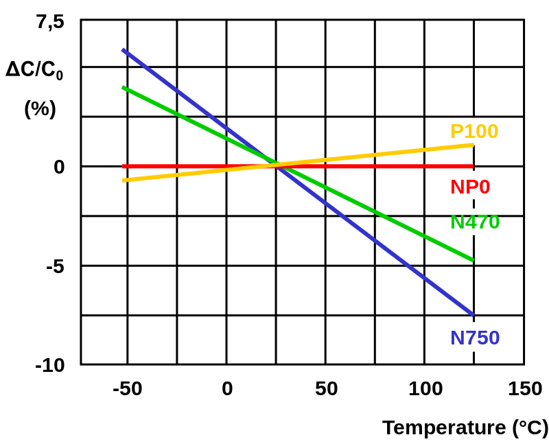
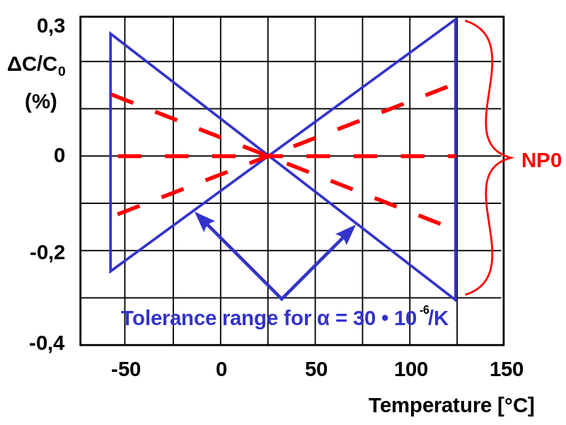
Idealized curves of different class 1 ceramic capacitors representation of the tolerance range of temperature coefficient α
Class 2 ceramic capacitors
Class 2 capacitors are made of ferroelectric materials such as barium titanate (BaTiOClass 2 ceramic capacitors have a dielectric with a high permittivity and therefore a better volumetric efficiency than class 1 capacitors, but lower accuracy and stability. The ceramic dielectric is characterized by a nonlinear change of capacitance over the temperature range. The capacitance value also depends on the applied voltage. They are suitable for bypass, coupling and decoupling applications or for frequency discriminating circuits where low losses and high stability of capacitance are less important. They typically exhibit microphony.
Class 2 capacitors are made of ferroelectric materials such as barium titanate (BaTiO3) and suitable additives such as aluminium silicate, magnesium silicate and aluminium oxide. These ceramics have high to very high permittivity (200 to 14,000), which depends on the field strength. Hence the capacitance value of class 2 capacitors is nonlinear. It depends on temperature and voltage applied. Additionally class 2 capacitors age over time.
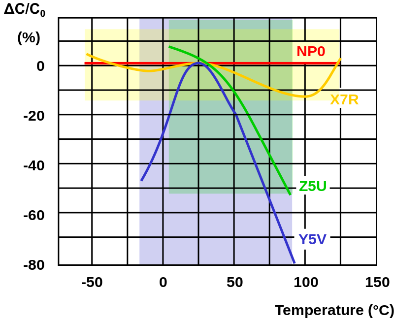
Class 2 ceramic capacitors with their typical tolerances of the temperature dependent capacitance (colored areas)
However, the high permittivity supports high capacitance values in small devices. Class 2 capacitors are significantly smaller than class 1 devices at the equal rated capacitance and voltage. They are suitable for applications that require the capacitor to maintain only a minimum value of capacitance, for example, buffering and filtering in power supplies and coupling and decoupling of electric signals.
Class 2 capacitors are labeled according to the change in capacitance over the temperature range. The most widely used classification is based on the EIA RS-198 standard and uses a three-digit code. The first character is a letter that gives the low-end operating temperature. The second gives the high-end operating temperature, and the final character gives capacitance change over that temperature range:
|
Letter code low temperature |
Number code upper temperature |
Letter code change of capacitance over the temperature range |
|---|---|---|
| X = −55 °C (−67 °F) | 4 = +65 °C (+149 °F) | P = ±10% |
| Y = −30 °C (−22 °F) | 5 = +85 °C (+185 °F) | R = ±15% |
| Z = +10 °C (+50 °F) | 6 = +105 °C (+221 °F) | S = ±22% |
| 7 = +125 °C (+257 °F) | T = +22/−33% | |
| 8 = +150 °C (+302 °F) | U = +22/−56% | |
| 9 = +200 °C (+392 °F) | V = +22/−82% |
For instance, a Z5U capacitor will operate from +10 °C to +85 °C with a capacitance change of at most +22% to −56%. An X7R capacitor will operate from −55 °C to +125 °C with a capacitance change of at most ±15%.
Some commonly used class 2 ceramic capacitor materials are listed below:
- X8R (−55/+150, ΔC/C0 = ±15%),
- X7R (−55/+125 °C, ΔC/C0 = ±15%),
- X5R (−55/+85 °C, ΔC/C0 = ±15%),
- X7S (−55/+125, ΔC/C0 = ±22%),
- Y5V (−30/+85 °C, ΔC/C0 = +22/−82%),
- Z5U (+10/+85 °C, ΔC/C0 = +22/−56%),
The IEC/EN 60384 -9/22 standard uses another two-digit-code.
| Code for capacitance change |
Max. capacitance change ΔC/C0 at U = 0 |
Max. capacitance change ΔC/C0 at U = UN |
Code for temperature range | Temperature range |
|---|---|---|---|---|
| 2B | ±10% | +10/−15% | 1 | −55 … +125 °C |
| 2C | ±20% | +20/−30% | 2 | −55 … +85 °C |
| 2D | +20/−30% | +20/−40% | 3 | −40 … +85 °C |
| 2E | +22/−56% | +22/−70% | 4 | −25 … +85 °C |
| 2F | +30/−80% | +30/−90% | 5 | (-10 … +70) °C |
| 2R | ±15% | − | 6 | +10 … +85 °C |
| 2X | ±15% | +15/−25% | - | - |
In most cases it is possible to translate the EIA code into the IEC/EN code. Slight translation errors occur, but normally are tolerable.
- X7R correlates with 2X1
- Z5U correlates with 2E6
- Y5V similar to 2F4, aberration: ΔC/C0 = +30/−80% instead of +30/−82%
- X7S similar to 2C1, aberration: ΔC/C0 = ±20% instead of ±22%
- X8R no IEC/EN code available
Because class 2 ceramic capacitors have lower capacitance accuracy and stability, they require higher tolerance.
For military types the class 2 dielectrics specify temperature characteristic (TC) but not temperature-voltage characteristic (TVC). Similar to X7R, military type BX cannot vary more than 15% over temperature, and in addition, must remain within +15%/-25 % at maximum rated voltage. Type BR has a TVC limit of +15%/-40%.
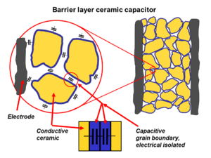
Class 3 ceramic capacitors
Class 3 barrier layer or semiconductive ceramic capacitors have very high permittivity, up to 50,000 and therefore a better volumetric efficiency than class 2 capacitors. However, these capacitors have worse electrical characteristics, including lower accuracy and stability. The dielectric is characterized by very high nonlinear change of capacitance over the temperature range. The capacitance value additionally depends on the voltage applied. As well, they have very high losses and age over time.
Barrier layer ceramic capacitors are made of doped ferroelectric materials such as barium titanate (BaTiO
3). As this ceramic technology improved in the mid-1980s, barrier layer capacitors became available in values of up to 100 μF, and at that time it seemed that they could substitute for smaller electrolytic capacitors.
Because it is not possible to build multilayer capacitors with this material, only leaded single layer types are offered in the market. [10] [11]
As of 2013 Barrier layer capacitors are considered obsolete, as modern class 2 multilayer ceramics can offer higher capacitances and better performance in a more compact package. As a consequence, these capacitors are no longer standardized by IEC.
